Drone Frame Optimization
December 2023
Through dual-load-case FEA, topology optimization, and targeted parametric studies, I reduced the drone frame from 788 g to 216 g while meeting all stress, displacement, and symmetry requirements. The final spoke-based design, developed in SolidWorks and ParetoWorks, remains both lightweight and practical to manufacture.
Design Optimization
The Process
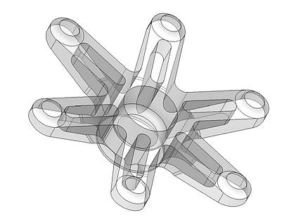
Design Envelope & Load Cases
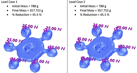
I began with FEA on the unmodified envelope to understand baseline behavior under the two required scenarios:
-
Hover Load – bottom face fixed, six 25 N loads applied at mounting pads.
-
Tilt Load – bottom face fixed, with asymmetric applied loads of 40/25/10 N across pad pairs.
Both analyses confirmed that the envelope’s stiffness and low stresses gave me a wide feasible space to remove mass safely.
Skills & Tools: Finite Element Analysis, SolidWorks


Topology Study
Using ParetoWorks, I ran a combined-load topology study to efficiently generate one solution that satisfied both scenarios.
Key constraints included:
-
≤35% final mass goal
-
Six-lobe symmetry
-
Preservation of nondesign regions
-
Max VM stress ≤3.2 MPa
-
Max displacement ≤5 mm
Across three identical studies, ParetoWorks consistently converged on a spoke-like design with tapered fins and thinning toward the outer rim. These features became the core architecture for my final part.
Skills & Tools: SolidWorks, ParetoWorks, Topology Studies
Parametric Optimization
Guided by the topology output, I built two levels of design studies to optimize mass through four key global variables.
Initial Study (~150 iterations):
Used coarse steps (~5 mm) to bracket feasible regions and understand how extreme values impacted stress and stiffness.
Refined Study (~80 iterations):
Used 1–2 mm step ranges around the optimal zone found in the first study.
Results showed:
-
A larger slot length and smaller inner radius reduced mass most effectively.
-
Fin thickness could safely decrease without compromising stiffness.
-
These insights established the geometric boundaries of the final frame.
Skills & Tools: Design Studies, Design Optimization


Design Validation
The final design achieved:
-
216.26 g total mass (27.4% of original)
-
3.183 MPa max VM stress (within target)
-
0.2069 mm max displacement (far below allowable)
Minor adjustments—like moving slots inward to avoid mounting-pad fillets and slightly thickening fins—ensured the final model met all nondesign constraints while keeping mass low.
Extra Consideration
Manufacturability Considerations
I evaluated both 3D printing and injection molding:
-
FDM 3D printing is practical for prototyping but would require support structures due to the underside taper, potentially affecting surface finish.
-
Injection molding better accommodates the underside geometry, though the through-slots complicate mold design.
-
The final geometry remains manufacturable with either method, depending on production scale!
